Overview
ViscoCorrectTM is a recent development in flow linearisation designed for use with the Webster VT series of turbine flow meters. ViscoCorrectTM allows VT type flow meters to be operated over a wide viscosity range whilst maintaining consistently good accuracy. This is achieved by monitoring fluid temperature to determine kinematic viscosity and using a custom dimensionless graph to calculate the true flow rate.
Background Information on Turbine Flow Meters
A turbine flow meter typically consists of a rotor mounted on a shaft fitted longitudinally within a housing. Fluid impacting on the turbine blades causes the turbine to rotate. A magnetic transducer mounted perpendicular to the shaft measures the passing of each blade. The relationship between flow and frequency is described by the meter factor, or K factor where:
K factor = frequency / flow (pulses per litre)
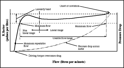
A typical K factor versus flow curve for a turbine flow meter is shown below.

Below approx. 20 lpm (dependent on flow meter size) a turbine flow meter is non-linear; this is characterised by a rapid increase in K factor and a pronounced 'hump'. At higher flows (above approx. 20 lpm) the curve becomes approximately linear, this region is known as the 'linear range'. The initial 'hump' shape of the curve is due to a combination of drag effects exerted on the turbine blade, specifically bearing friction, magnetic detent, and viscosity effects. Bearing friction is minimised by the use of precision ball-race bearings. Magnetic detent, the effect of magnet drag due to the inductive transducer attracting the turbine blade, is minimised by using a magneto-resistive type transducer and associated electronics. The third source of drag is influenced by the viscosity properties of the fluid being measured.
K factor Linearisation
At the simplest level, K factor linearisation involves dividing the frequency signal from the flow meter by a constant K factor to compute the volume flow rate. Whilst this method is quite effective over the short linear range of the turbine it severely limits the turndown ratio of the flow meter. In order to extend the flow range whilst maintaining accuracy, K factor linearisation was improved to include a fifteen point K factor versus flow curve, similar to the one shown on the previous page. This method is very effective and provides accuracy of 1% of indicated reading over a 100:1 turndown ratio, i.e.: one flow meter can measure from 4 to 400 lpm.
Limitations
A K factor versus flow curve for a particular turbine flow meter is highly repeatable assuming it is operated and calibrated using the same fluid at the same temperature. These limitations are due to the effect of changes in viscosity on the performance of the turbine flow meter, particularly at low flows as previously mentioned.
Kinematic viscosity = absolute viscosity / density (cSt or mm2/s)
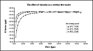
Kinematic viscosity of a mineral oil is dependent on both temperature and pressure. A change in pressure can lead to a small change in kinematic viscosity, typically though, for working pressures under 100 bar the effect is minimal. A change in temperature however, is more important as an increase in temperature results in a decrease in kinematic viscosity. A typical mineral oil used in the fluid power industry will have a kinematic viscosity of 32 cSt at 40ƒC but a viscosity of over 80 cSt at 20ƒC. Changes in viscosity effect both the shape and the vertical offset of the K factor versus flow curve. The example below shows a turbine flow meter tested on the same oil, ISO 32, at three different temperatures.

To obtain optimum accuracy, turbine flow meters that use K factor linearisation must be used under very strict fluid and temperature conditions dictated by the manufacturer.
ViscoCorrectTM
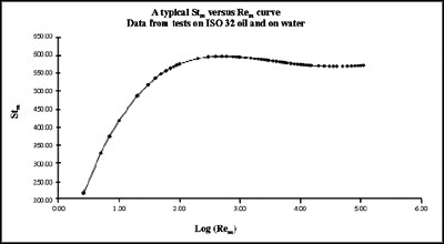
ViscoCorrectTM is a refined method of K factor linearisation that allows you to accurately measure flow over a wide range of viscosities. This means one turbine flow meter can be used on a variety of different fluids and over a range of temperatures, allowing you to choose your own test criteria.The linearisation curve is created from a series of tests carried out over a range of different viscosities and flows. The resulting data is plotted against custom axes, the y-axis uses Stm, a dimensionless form of the K factor, whilst the x-axis uses Rem, a modification of the Reynolds number. Because Rem includes both frequency and kinematic viscosity, the tests carried out at different viscosities can be plotted together in one smooth curve. Since the axes are dimensionless, linearisation curves for different sizes of turbine flow meter can be combined together. Once calibrated, a VT type turbine flow meter measures the fluid temperature and sends this signal along with the turbine frequency to the C1000 data acquisition system. Using a look-up table for the fluid under test, the kinematic viscosity is quickly obtained from the temperature. Frequency, kinematic viscosity and constants defining the flow meter characteristics are combined to calculate Rem. A mathematical model of the linearisation curve (shown below), stored within the C1000 evaluates the corresponding Stm value. The frequency and Stm value are then used to calculate the true volume flow rate.


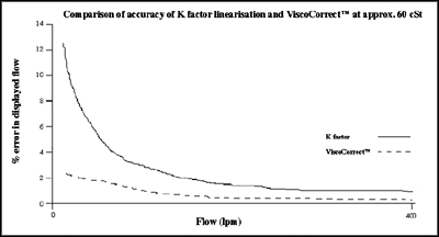
ViscoCorrectTM is extremely effective at lower viscosities, typically providing accuracy better than 1% of indicated flow for viscosities between 1 and 40 cSt (highlighted in grey in the table below). For viscosities between 40 and 60 cSt ViscoCorrectTM still provides considerable improvements in accuracy over K factor linearisation, this is demonstrated in the picture above, where the displayed error has been reduced from approx. 12 % to approx. 2% for a test at 60 cSt.
Look-up table to calculate kinematic viscosity (cSt) of mineral oils at specific temperatures
Viscosities highlighted in grey indicate turbine flow meter accuracy of better than 1% of indicated reading (VT Range).
Fluid type
Temp. °C |
ISO 15 |
ISO 22 |
ISO 32 |
ISO 47 |
ISO 56 |
ISO 68 |
Kerosene |
|
0 |
85.9 |
165.6 |
309.3 |
449.9 |
527.6 |
894.3 |
3.5 |
|
10 |
49.0 |
87.0 |
150.8 |
204.7 |
244.9 |
393.3 |
2.8 |
|
20 |
30.4 |
50.5 |
82.2 |
105.5 |
127.9 |
196.1 |
2.3 |
|
30 |
20.1 |
31.6 |
48.8 |
59.8 |
73.1 |
107.7 |
2.0 |
|
40 |
14.0 |
21.0 |
31.0 |
36.6 |
44.9 |
63.9 |
1.7 |
|
50 |
10.2 |
14.7 |
20.8 |
23.9 |
29.4 |
40.5 |
1.4 |
|
60 |
7.7 |
10.7 |
14.7 |
16.5 |
20.2 |
27.2 |
1.3 |
|
70 |
6.0 |
8.1 |
10.9 |
12.0 |
14.6 |
19.2 |
1.1 |
|
80 |
4.8 |
6.4 |
8.4 |
9.1 |
11.1 |
14.3 |
1.0 |
|
90 |
4.0 |
5.2 |
6.6 |
7.2 |
8.7 |
11.1 |
|
|
100 |
3.3 |
4.3 |
5.5 |
6.0 |
7.1 |
8.9 |
|
|
110 |
2.9 |
3.6 |
4.6 |
5.1 |
5.9 |
7.5 |
|
|
120 |
2.5 |
3.2 |
4.0 |
4.4 |
5.1 |
6.4 |
|
ISO 15, 22, 32, 46 and 68 based on typical figures for the Esso Nuto range of HM oils. ISO 37 based on Shell Tellus HM oil. Typical figures used for Kerosene. |
|